A: Verifying Proper Operation:
BEFORE OPENING A PANEL, TURN POWER OFF! SAFETY PROCEDURES STILL APPLY: - Before working on an electrical conductor, verify zero electrical energy with proper voltage testing instrument and the proper procedure as per NFPA 70E Article 120.5.
- TURN POWER OFF. All indicators should be extinguished. Note: If only a single LED illuminates for any (2) indicator pairs, STORED ENERGY is likely present and must be removed or discharged. All indicators must be extinguished or a shock hazard is present on the monitored lines.
- A clear view of the front indicator window must be maintained. Removal of dust, grime, or other contaminants should performed by gently wiping them off with a clean damp cloth. Do not use harsh chemicals
- First disconnect all equipment that may introduce a hazard and notify personnel before powering the panel!
- Periodic inspection of the O-Ring is recommended. Verify the inside contact surface around the panel knockout is clean, flat and free of debris.
- Nut Torque: The nut tightening torque required to maintain seal with full O-ring compression is
about 10 in-lbs. However, this torque level can still allow the housing to be manually rotated.
Tightening torque must be increased further to around 15 to 30 in-lbs in order to restrict rotational
movement to a minimal amount. With moderate rotational hand force, it is normal for the O-ring
to allow a little cushioned amount of back and forth movement but should not allow continued
rotation.
- TURN POWER ON. With up to 600V 3 Phase applied, the L1, L2, and L3 indicators should flash or glow according model respective to “FLASH RATE” Specifications below. The type of power system grounding configuration determines if the GND indicator normally indicates.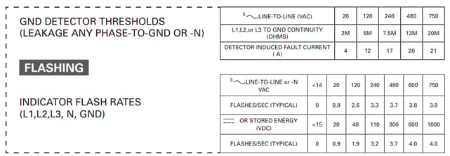
- Use this procedure to insure proper grounding:
a. Complete normal installation and apply power to the Voltage Indicator, if the GND LEDs do not illuminate, proceed to step b.
b. Remove power and re-establish an electrical safe work condition to allow one phase lead-wire to be disconnected from its source by either disconnecting wire or pull a fuse.
c. Re-apply power and verify that the GND LEDs and Neutral (N) LEDs for Wye models now illuminate. If not, remove power & provide current with a 1M-2M ohm 1W resistor temporarily connected from any phase to ground. Repeat step c.
d. To complete installation, disconnect power before removal of step c.) resistor & to restore the phase lead-wire or fuse. Re-apply power to re verify that L1, L2, & L3 LEDs illuminate.